LAB 11: Localization (Real)
Background
At the end of lab 10, we succesfully implemented a Bayes filter to localize a robot within a simulated environment. The Bayes filter used an update step (relies on the sensor model) and a prediction step (relies on the odemetry model) to localize the robot. Optimized implementations are provided in the Localization class which implements the Bayes filter.
In lab 11, we will localize the robot within a real environment. However, since the robot's movement is very noisy, we will not have an odometry model for the prediction step. Instead, localization will depend on the update step based on TOF sensor readings. We need to implement the RealRobot class's perform_operation_loop method. The perform_operation_loop method should trigger a 360-degree turn of the robot, with TOF measurements taken throughout the turn.
Implementation
Artemis Code
To take TOF measurements at specific angles within the robot's 360-degree turn, we need to control the yaw of the robot. The DMP is used to obtain yaw readings from the robot's IMU (see setup in Lab 6). The pid_yaw_control function from Lab 6 is also reused to control the yaw of the robot with the PD controller.
Whenever the YAW_CONxTROL command is sent over BLE, the following conditional within the main BLE loop is executed.
The first call to pid_yaw_control calculates and sets the PWM duty cycle to rotate the robot towards the target yaw. Whenever the robot's yaw is within 3 degrees of the target yaw and the target_reached flag is not true, we perform a blocking read from the TOF sensors and add the TOF reading to a data packet. The target_reached flag is then set to true to ensure we only record one TOF reading for each target yaw. This could be improved by taking multiple readings per target yaw and averaging them, but this was not necessary to achieve accurate localization for my robot.
The robot code implementation has no sense that it is performing a 360-degree turn. It is only concerned with turning to a specific yaw and taking a TOF reading.
PERFORM_OBSERVATION_Loop
The perform_observation_loop function steps the robot through a 360-degree turn and parses the TOF and yaw received from the robot. The code below steps the robot through the 360-degree turn in 15 degree increments. The world.yaml file is modified to set the observation_count parameter to 24 so the Bayes filter expects 24 TOF readings in 15 degree increments. The arguments in the YAW_CONTROL command set various parameters for the PD yaw controller (see lab 6). The call to time.sleep(1) gives the robot time to rotate to the target yaw before a new target yaw is sent.
Once all TOF readings have been taken, the perform_observation_loop function sends a SEND_YAW_MAPPING_DATA command to signal the robot to send the TOF readings and corresponding yaw measurements over BLE. Similar to previous labs, a data handler is used to parse the incoming packets. The definition and call to async def sleep_for_5_secs() gives time for all packets to be sent over BLE. The async keyword is added to the perform_observation_loop definition and the await keyword is added to perform_observation_loop calls. This allows for perform_observation_loop to perform asynchronous non-blocking waits while data is sent over BLE.
Once all data is received, the yaw measurements and the corresponding TOF readings are returned in numpy arrays. The entire function definition is shown below.
Simulation Results
Virtual Robot
Localization is first tested in simulation with a simulated robot. The final plot with odometry model predictions, ground truth, and belief is shown below.
Real Robot
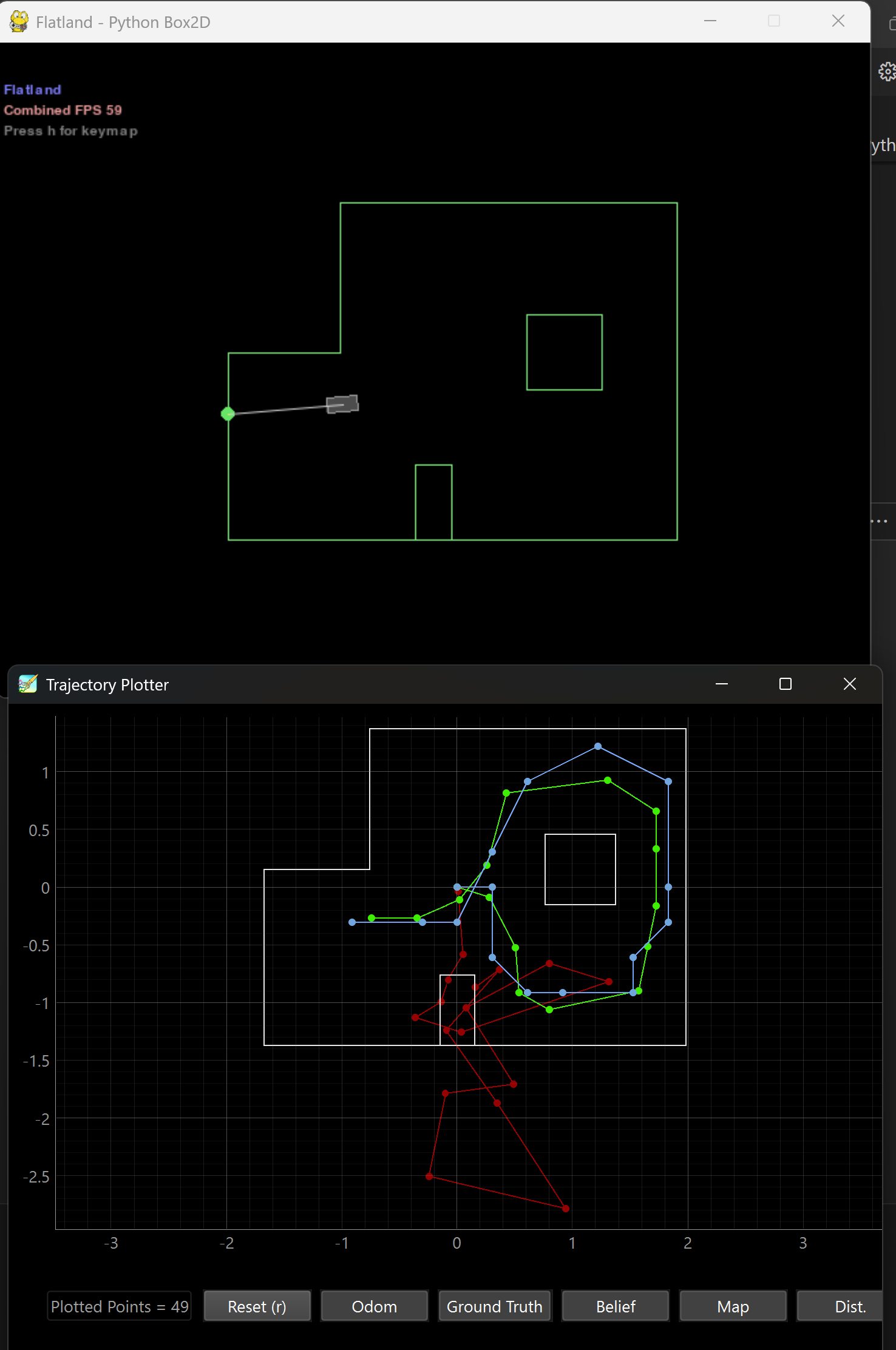
The real robot is tested within an environment at 4 different locations. The plots below show the localized poses (blue) with respect to the ground truth (green).
(-3, -2)
In this position, the localized pose is directly on top of the ground truth.
-plot.png)
-data.png)
The robot localized itself perfectly in this position for the x and y positions (within the grid resolution). However, the angle belief is off. Looking at the map, the TOF reading near 170 degrees (counterclockwise) closely reflects the TOF reading at 0 degrees. Furthermore, the robot did not rotate fully back to its original position, so it would not have seen the somewhat small TOF reading at 0 degrees. Had it seen this small TOF reading, I believe 170 degrees would have been ruled out due to 180 degrees having a large expected TOF reading.
(0, 3)
-plot.png)
-data.png)
The robot localized itself decently well in the x and y positions. Again, the angle measurement is off. The TOF reading at 150 degrees closely resembles the TOF reading at 0 degrees.
(5, -3)
-plot.png)
-data.png)
The localization is somewhat off from the ground truth. This could be due to the robot not rotating perfectly on-axis in this case. I believe the robot's battery was running low, causing motor behavior to be different.
(5, 3)
-plot.png)
-data.png)
As with the previous position, the localization is somewhat off from the ground truth. As these last two positions were measured last, the robot's battery was still running low, causing the robot to turn poorly on its axis. This drift could be the reason for the poor localization.
Discussion
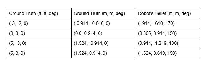
A table of ground truth values versus the localized poses is shown below. The localized poses are reasonably close to the ground truth values. Before lab 12, localization results can be improved with several methods:
- Increasing and averaging the number of samples taken at each target yaw to reduce the effect of sensor noise.
- Refining the PD controller parameters for more accurate yaw orientations.
- Ensuring that the TOF sensor is pointed at an angle high enough to not read the floor.
- Tuning the sensor noise parameter.
For all positions, the angle belief is significantly off from the ground truth. While I am still unsure of the exact reasoning for this, some possible explanations are: