LAB 6: ORIENTATION CONTROL
PRELAB
An effective debugging system is helpful for tuning and implementing a closed-loop controller. The debug interface used is a Bluetooth Low Energy (BLE) connection. Data is sent from the Artemis to a Jupyter Lab instance where data is processed and visualized.
Sending data over BLE during a control loop is computationally expensive. To increase the frequency of the control loop, data is stored in a buffer and sent over BLE after a control task is finished. The buffer is then cleared and the process repeats.
Below is the definition of the YawControlPacket and the associated YawControlDataBuffer. The packet contains all relevant data seen by the controller.
This packet is populated by a record_yaw_pid_data(...) function. This function is called during each control loop and populated with the most recent data.
After a control task is done executing, the sendControlData(...) function then writes the data in the ControlDataBuffer over the BLE connection.
In Jupyter Lab, a Python function reads and parses the sent strings. The data is parsed into Python arrays.
The data can then be plotted with Python libraries to easily visualize the data for debugging.
Digital Motion Processing (DMP)
The integral of the gyroscope reading is used to calculate the car's orientation. The gyroscope measures the rate of rotation, and by integrating this rate over time, the orientation angle can be determined. For roll and pitch, the accelerometer readings can be fused with gyroscope measurements with a complementary filter to mitigate drift and lower noise. However, the yaw angle cannot be calculated with the accelerometer due to gravity being parallel to the yaw axis. To minimize yaw drift, the digital motion processor (DMP) is used. The DMP is setup according to this guide.
To prevent the DMP FIFO buffer from overflowing, data from the DMP is read with the readDMPYaw() function every time the loop() function is executed. The readDMPYaw() function calcualtes the yaw from the quarternion components output from the DMP. readDMPYaw() function calcualtes the yaw from the quarternion component data from the DMP. The yaw is then stored in a global variable.
According to the IMU datasheet, the gyroscope can measure +/- 250 dps, +/- 500 dps, +/- 1000 dps, and +/- 2000 dps depending on the programmable GYRO_FS_SEL register configuration. These specifications are enough for our application.
Designing a PD Controller
Infastructure
To make tuning the controller easier, parameters such as P_GAIN, D_GAIN and target_yaw are configurable at runtime. The controller executes within the loop() function, allowing for bluetooth commands to be processed while the controller is running. This means the setpoint, gains and other parameters can be adjusted without stopping the controller.
To start and stop the controller, the YAW_CONTROL command takes in an argument that acts as a flag for starting the controller. Similarly, the RECORD_PID_DATA signals the controller to log data with the record_yaw_pid_data(..).
The control interface is modified to include turnLeft(..) and turnRight(..) functions. Corresponding BLE commands are added to allow for the car to turn left or right to tune the speed offsets to allow the car to perform tight turns.
P Controller
One issue is determining whether to turn left or right based on whether the target angle is closer by going clockwise or counterclockwise. This requires calculating the shortest angular distance between the current orientation and the target orientation. This determination is made with the following algorithm:
The step function for the P controller is shown below. The shortet angular distance is calculated using the algorithm above, and the error is scaled by the P_GAIN term. Depending on if the shortest path is in the clockwise or counter-clockwise direction, the car is turned left or right.
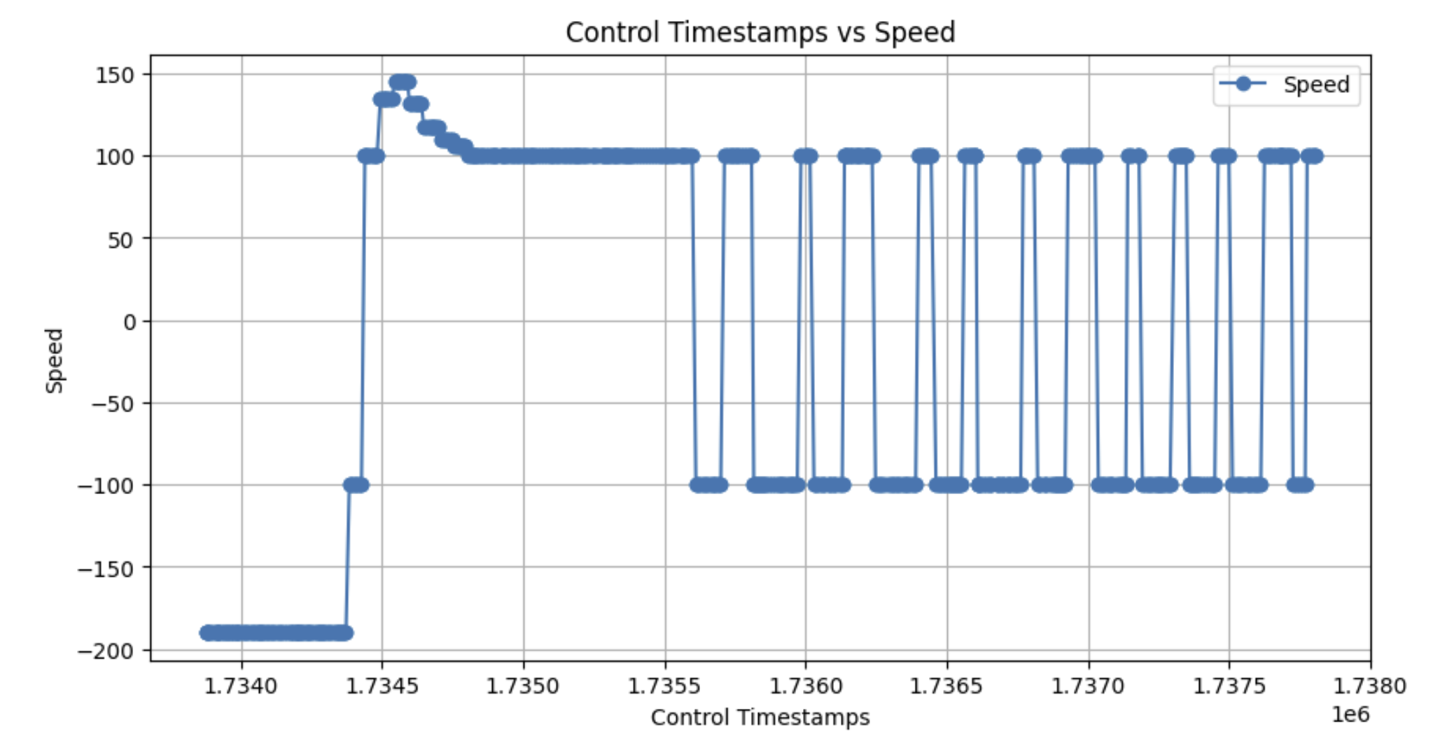
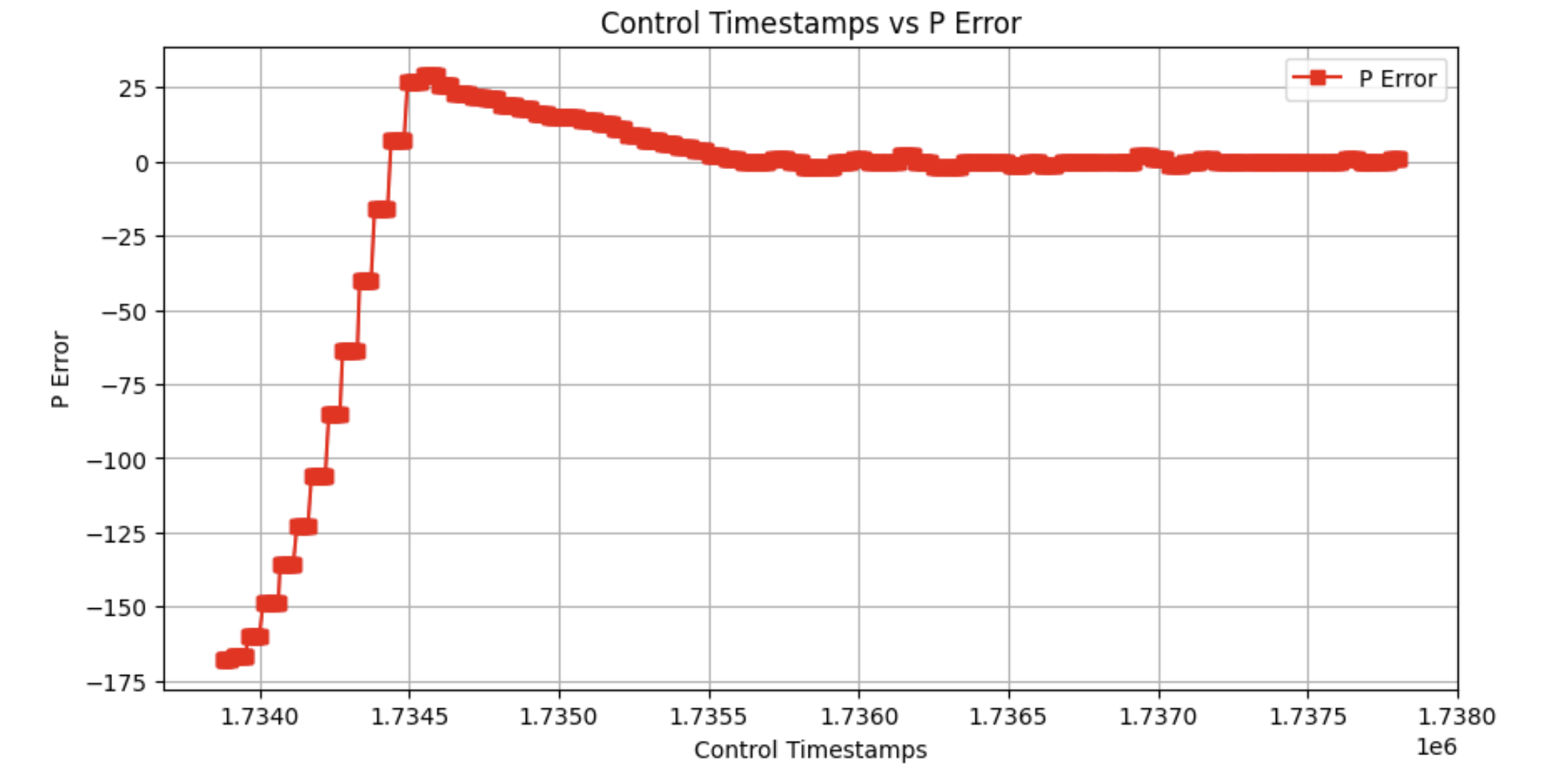
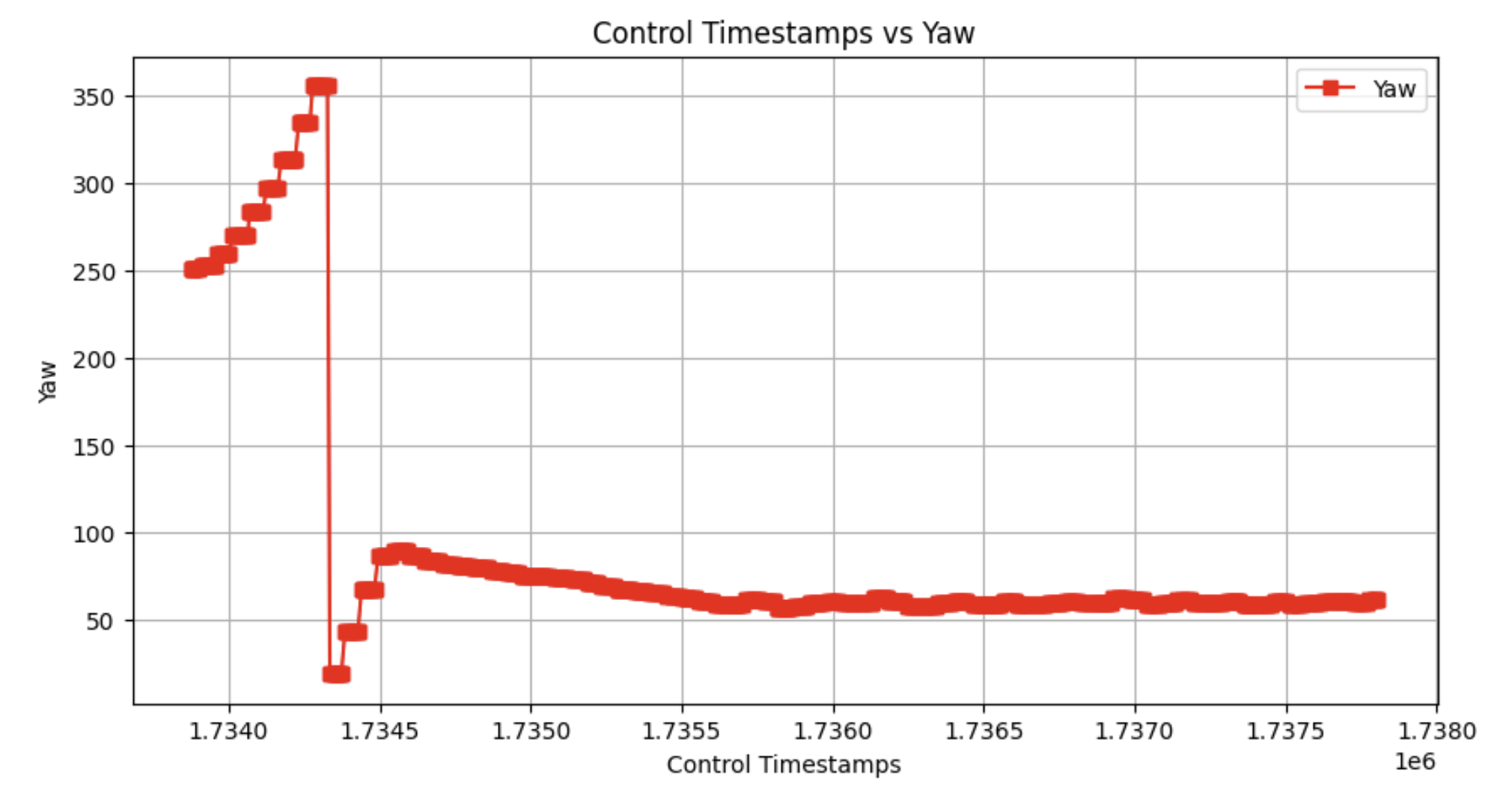
The videos below demonstrate the P Controller's perforamnce on carpet and a wood floor. The P_GAIN is set to 8. Lower P_GAIN values lead to slower responses, while higher values lead to additional overshooting.
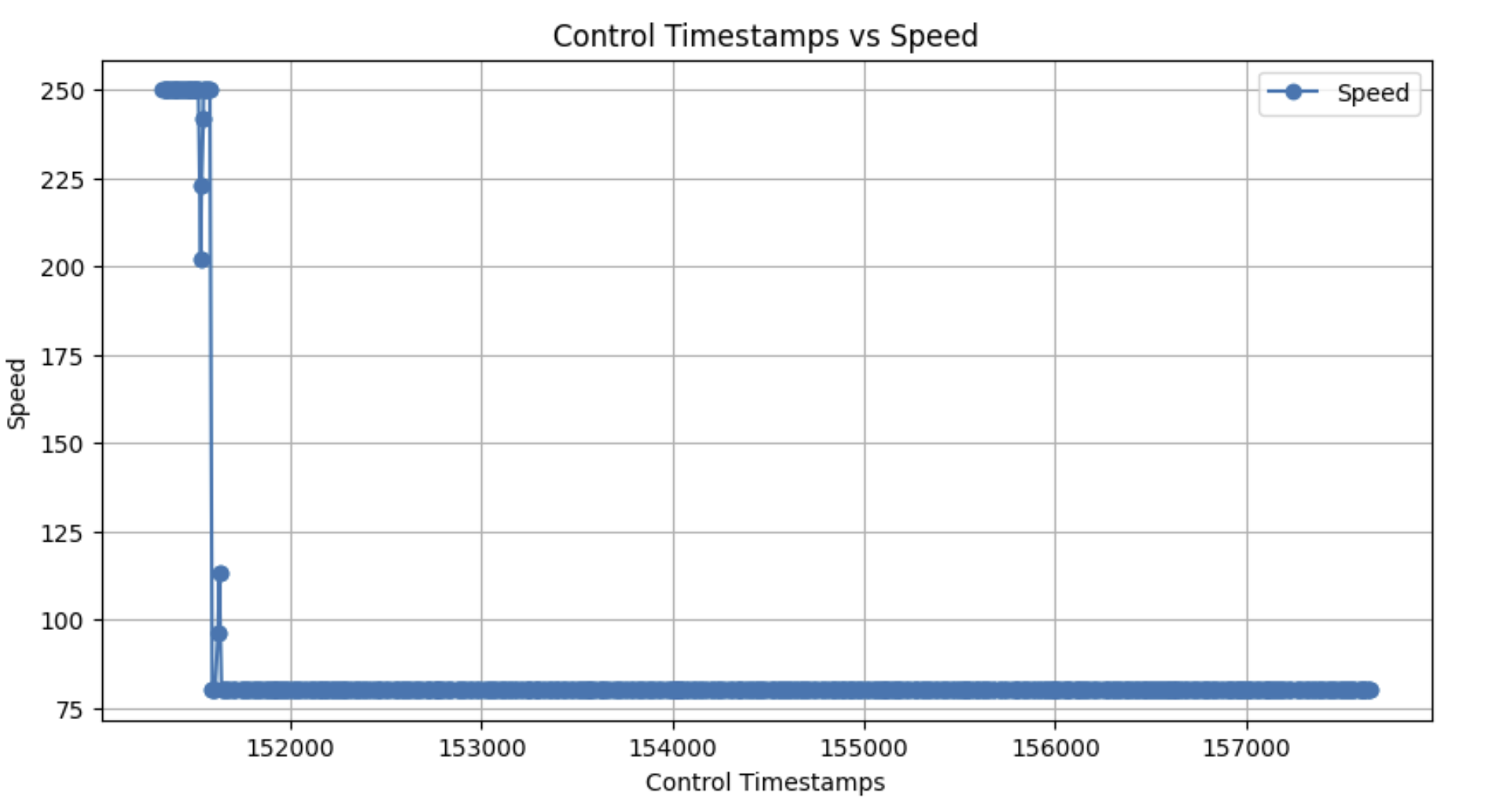
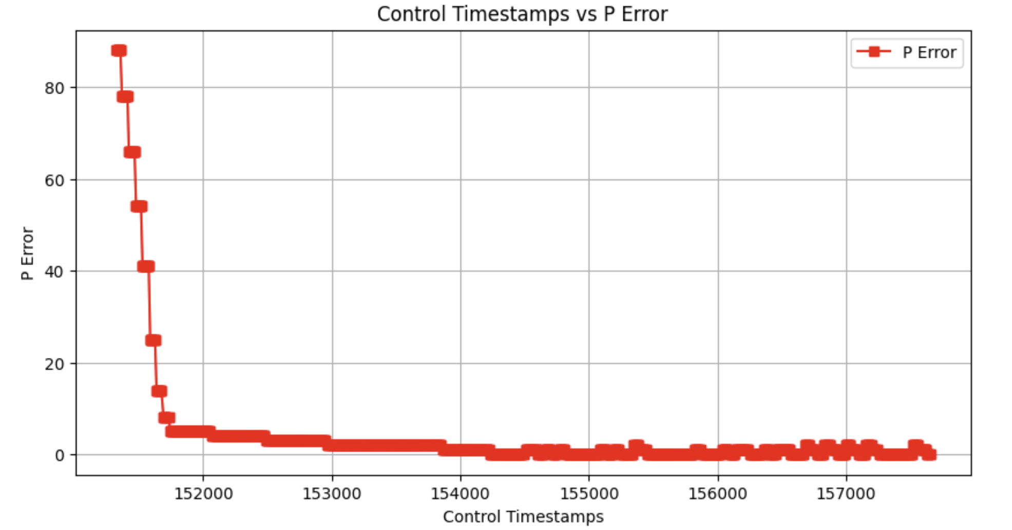
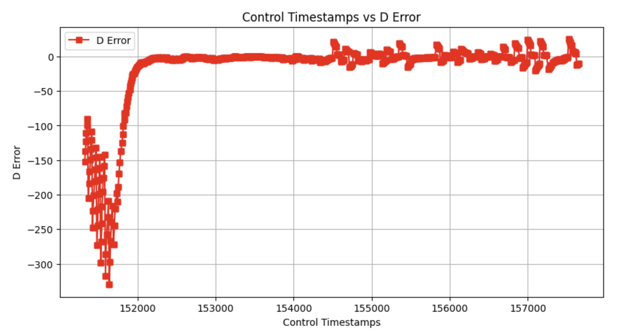
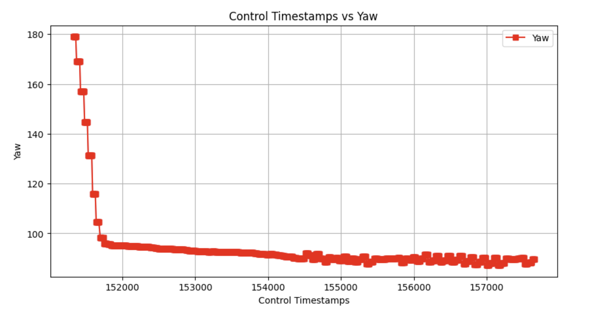
The graphs below show the car's speed, proportional error, and orientation over time. With a Kp of 8 and a setpoint of 60 degrees, The P Controller quickly approaches but overshoots the target setpoint and oscillates around the setpoint. Note the wrapping from 360 to 0 in Figure 5 is a result of the scaling of yaw readings to a 0-360 degree range.
PD Controller
To reduce the overshooting and oscillations seen in the P controller, a PD controller is implemented. The PD controller uses the derivative of the error to act as a dampening term as the car approaches the setpoint. The derivative term is calculated by taking the difference between the current error and the previous error and dividing by the time elapsed between the two errors.
Taking the derivative of the change in yaw (which is the same as the change in error) is the same as the gyroscope output since the gyroscope output is integrated to find yaw. However, for ease of implementation, the derivative term is calculated directly using the DMP yaw. This extra calculation did not result in a noticeable difference in the controller's speed.
Taking the difference between only two error measurements can be noisy. Furthermore, changing setpoints can cause derivative kick as the change in error has a large instantaneous change. To reduce noise and the effect of derivative kick, the derivative term is passed through a low-pass filter. The three additional lines needed within the control loop are shown below. Instead of directly keeping track of the time between control loop executions, the average time between control loop executions is used. Line 3 is the low pass filter with configurable alpha to adjust the degree of filtering.
The videos below demonstrate the PD Controller's performance on carpet and when the car is interfered with. The P_GAIN was set to 8 and the D_GAIN was set to 0.5. Lower D_GAIN values lead to overshooting, while higher values lead to a slower response.
The graphs below show the car's speed, proportional error, derivative error, and yaw over time at a setpoint of 90 degrees. With the derivative term added, there is noticeable reduced overshooting.
Considering an Integral Term
The integral term was deemed unnecessary for the controller. The integral term is useful when the car fails to reach the setpoint. However, the car's consistently reaches the setpoint within reasonable time.
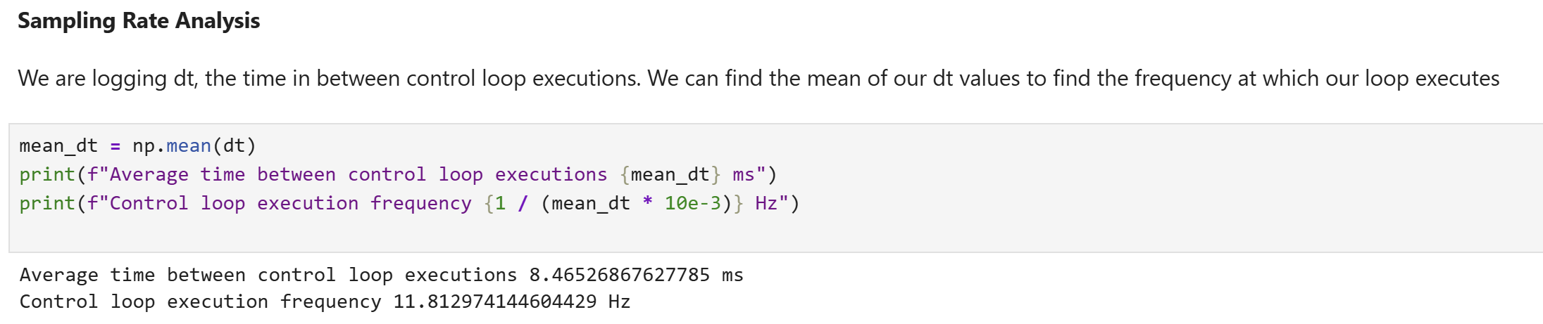
Range/Sampling time discussion
A quick execution time of the control loop is essential for a responsive controller. While the exeuction time was limited by the TOF sensor in lab 5, the DMP outputs at rates up to 55 Hz. The control loop is only limited by its own computation time.
To characterize the control loop's exeuction time and frequency, the time between control loop executions is passed as part of the YawControlPacket data. The mean of this data is the average time between control loop executions, the control loop's frequency can be calculated.