LAB 4: Motors and Open Loop Control
PRELAB
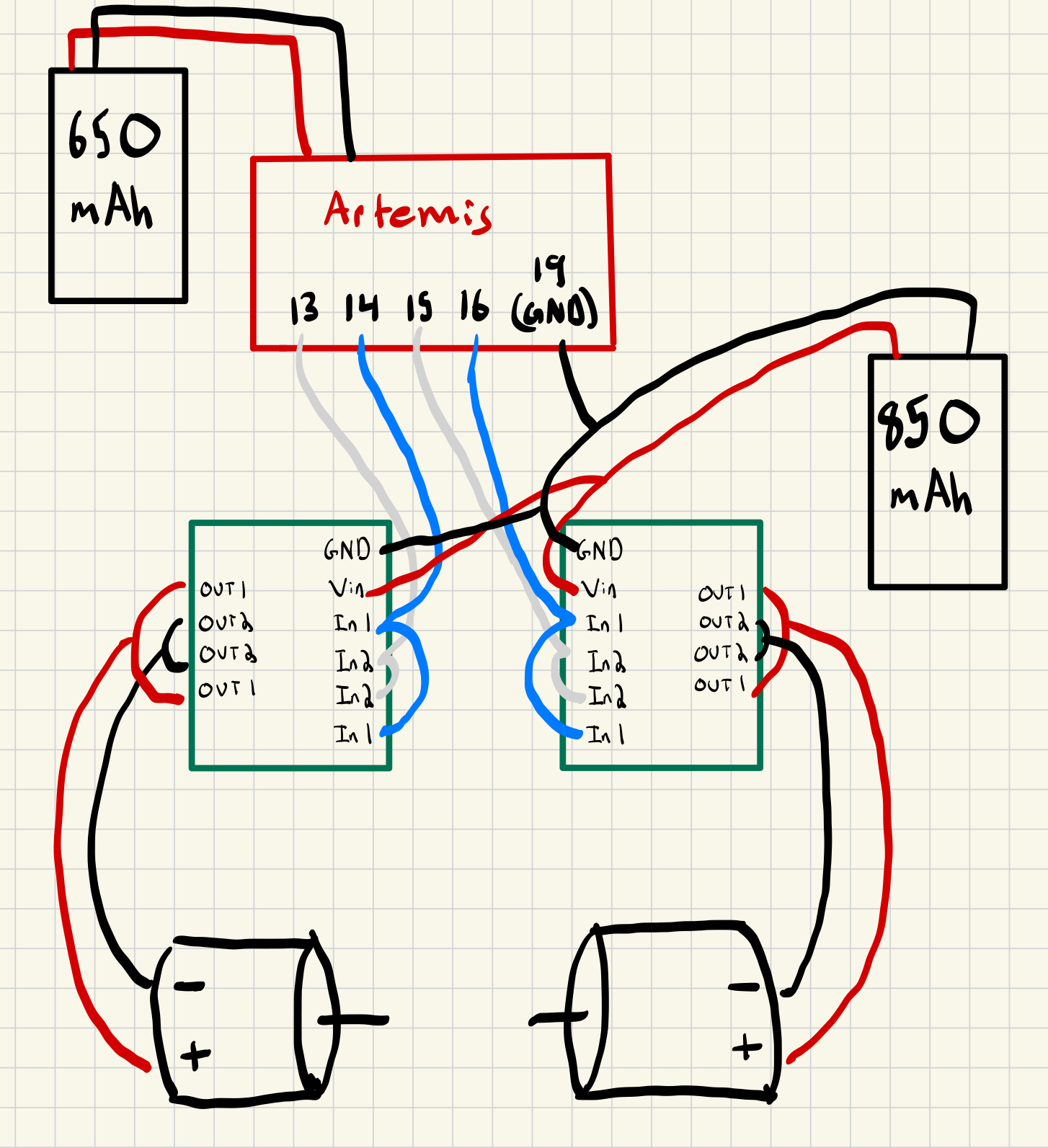
Pins 13, 14, 15, 16 are used to control the two motor drivers. The wiring diagram of the motor drivers is shown below. The Artemis Nano and Apollo3 pinout schematics were consulted to find pins capable of PWM outputs. The A and B input and output channels are coupled together to drive one motor to increase the total current output. The TOF and IMU sensors are excluded.
The Artemis is powered by a dedicated 650 mAh battery while the motor drivers are powered from a 850 mAh battery. Since the current draw of the motor drivers is high, having a dedicated power supply for the Artemis ensures that the Artemis does not reset due to voltage drops. To reduce EMI interference, wire lengths are kept short.
Testing Motor Drivers
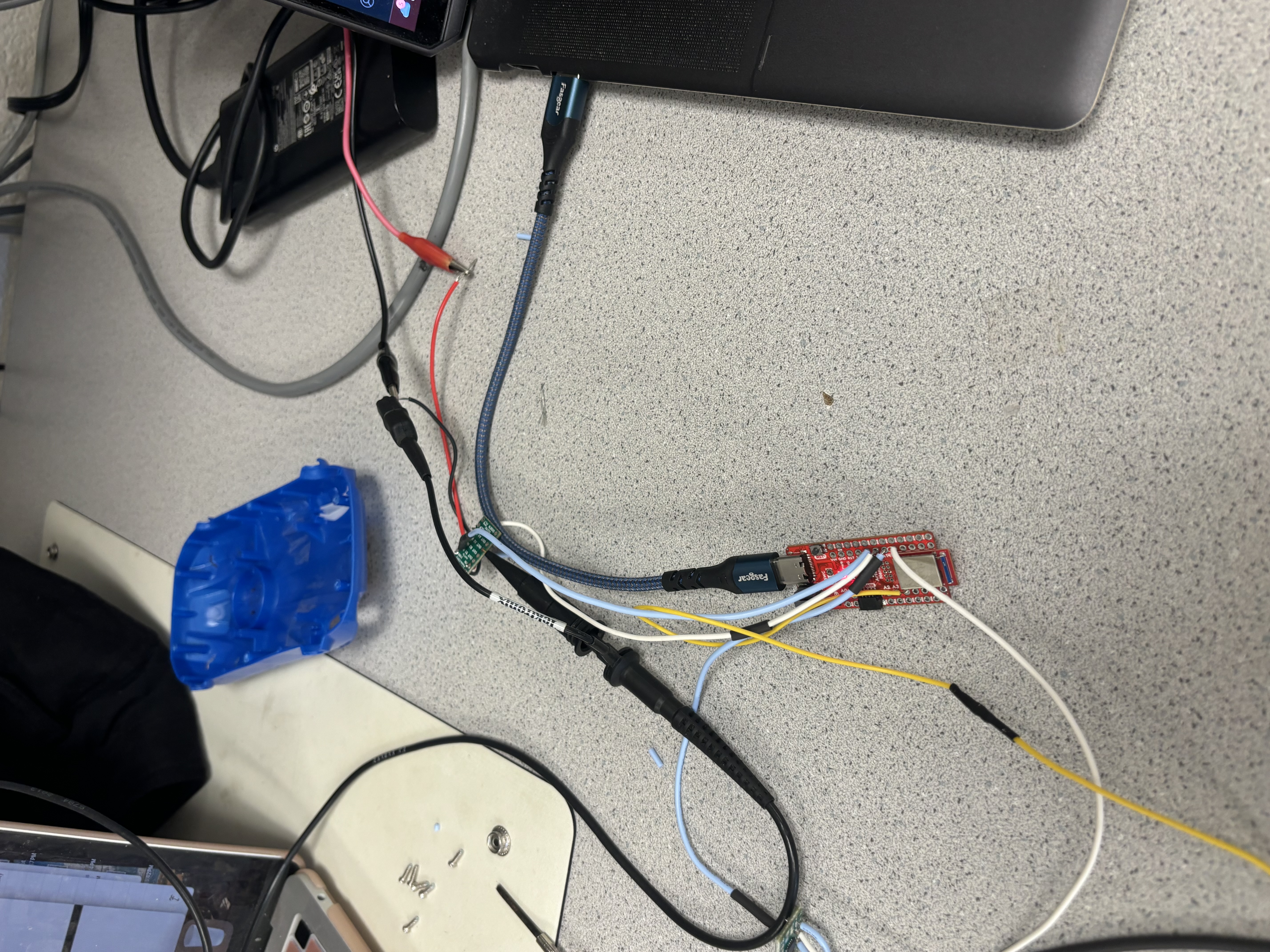
Before permanently assembling electronics into the car chassis, the dual motor drivers are each tested to ensure they can provide PWM output. A DC power supply is used to power a motor driver and the output is checked with an oscillopscoe for this initial test. The OUT1 and OUT2 pins are conected to the oscillopscoe probes.
Power supply discussion
The DC power supply was set to 3.7V. Although the drivers accept up to 10.8V (datasheet), 3.7V is chosen to simulate the voltage of the 850 mAh battery.
The setup is shown below. In the figure, the motor driver is being controlled from pins 15 and 16 on the Artemis and the OUT2 pin is being scoped.
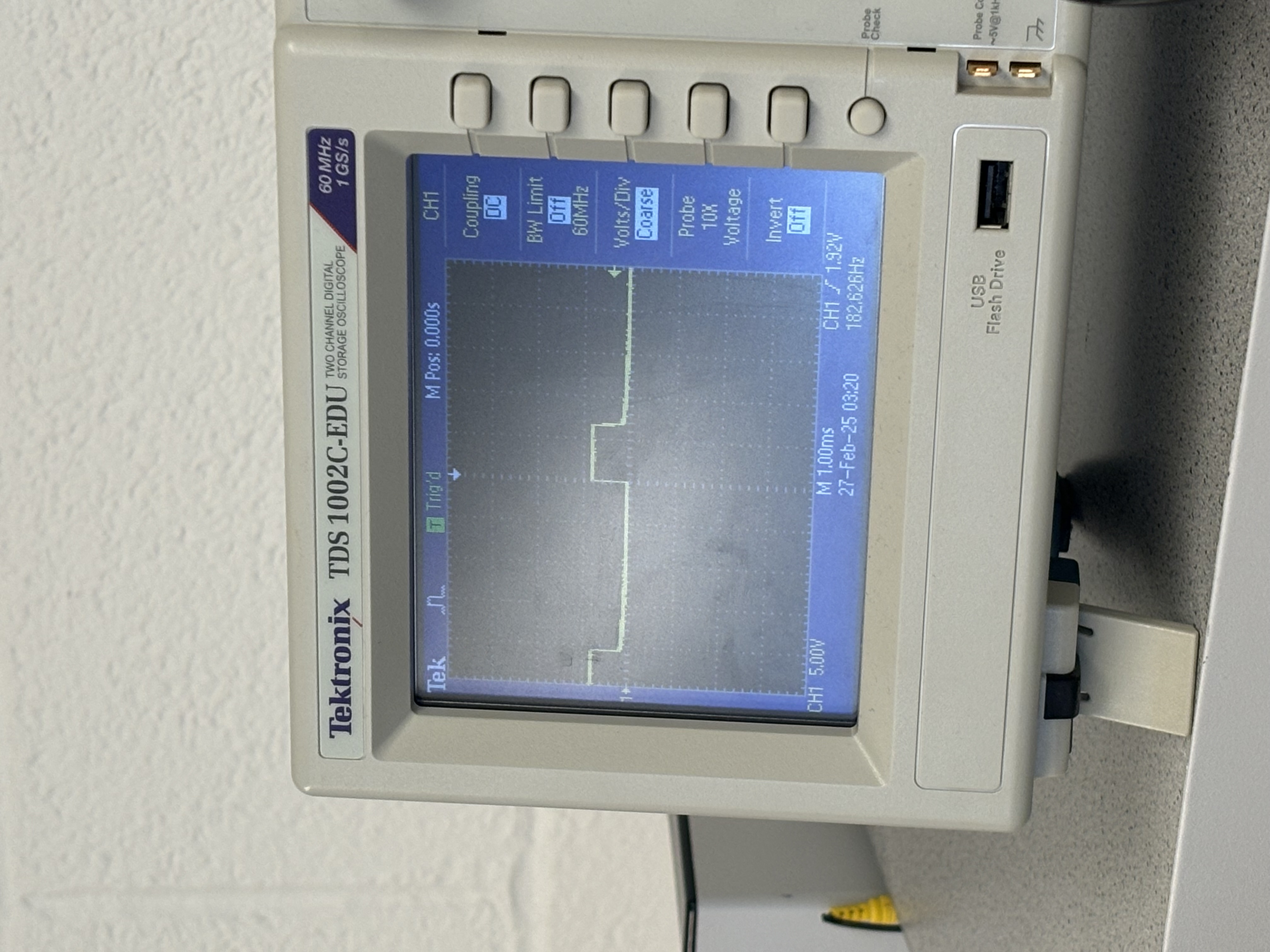
With the setup above, the analogWrite(15, 63) and analogWrite(16, 0) commands send a PWM with 25% duty cycle to the motor driver. The code and oscilloscope output on the OUT2 pin are shown below.
Once the oscilloscope confirms that the motor drivers are outputting the correct PWM signals, the motor driver outputs are soldered to the car wheel motors. The video below demonstrates the car's left wheels spinning with the code below. The motor drivers are still being powered from the DC power supply.
To test both motors on the 850 mAh battery, the lines controlling the right motor are uncommented. The Vin and GND ports of the dual motor drivers are connected to the positive and negative terminals of the 850 mAh battery. The video of both motors spinning on battery power is shown below.
Car Assembly
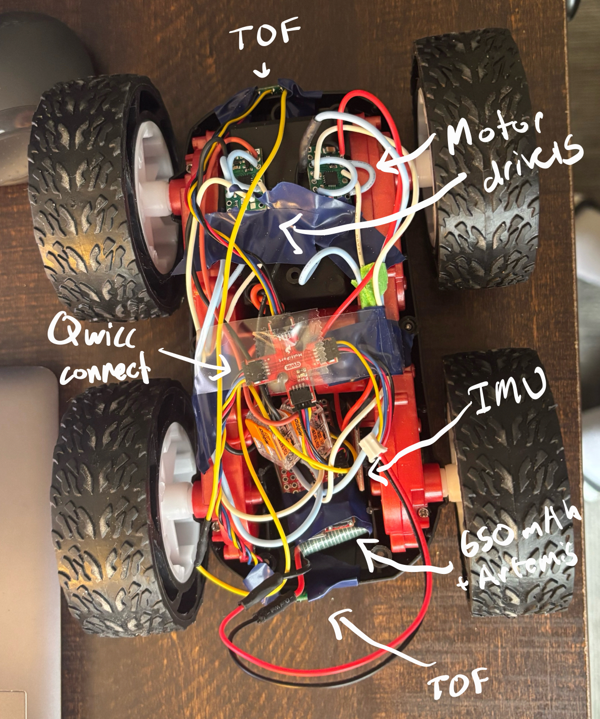
With the motor drivers tested, the electronics can be assembled into the car chassis. The TOF sensors are mounted at the front and back of the car. The 850 mAh battery is stored in the battery compartment. The Artemis board, 650 mAh, and IMU are in the compartment that housed the original car control board. The motor drivers are mounted on the backside of the battery compartment. Electrical tape is used to secure wires and physically secure the electronics. Zip ties may be added in the future to further secure the wires to the chassis.
Calibration
Lower limit PWM discussion
The lower limit PWM is the minimum PWM duty cycle that causes the car to move. The lower limit PWM is found by slowly incrementing the PWM value until the car moves. This value was found to be around an analogWrite of around 40, or a 16% PWM duty cycle. However, testing was conducted with a battery that had been previously used for testing. With a freshly charged battery, an analogWrite of 45, or a 17.6% PWM duty cycle was able to start the car from rest.
An in-place turn required an analogWrite of 60, corresponding to a 23.5% PWM duty cycle.
Calibration Factor
Initially, the analogWrite values for both motors were set to the same value. The result of this test is shown below. The car veers to the right. This could be due to the car being unbalanced or the motors having different characteristics. To correct this, the left motor is set to a lower analogWrite value. The car now moves straight. The calibration factor is the ratio of the left motor analogWrite value to the right motor analogWrite value in order for the car to go straight. The calibration factor was found to be 0.9.
Open loop control via BLE
To control the car via BLE, new commands MOVE_FORWARD, MOVE_BACKWARD, TURN_RIGHT, and TURN_LEFT are added. A control.ino file is defined to define the implementation details of these commands. The bluetooth command handler seen in previous labs then calls these functions to execute movements based on incoming bluetooth commands.
The control.ino file is shown below with implementations for each of the new commands. Currently, the values will be set by the incoming bluetooth command. The LEFT_A, LEFT_B, RIGHT_A, RIGHT_B, time_ms, and CALIBRATION_FACTOR are macros defined in the control.h file. They are 13, 14, 15, 16, 750, and 0.9 respectively
Turns are implemented by setting the left or right motor driver to a much larger value than the other driver. Through experimentation, suitable values for a left and right turn were found.
The new cases within the handle_command function within our bluetooth interface is shown below.
The video below demonstrates open loop, unthethered control of our car via BLE.
Discussion
Much of this lab involved soldering and assembling hardware. Thus, much of the success and reliability of the end product relied on the quality of the assembly. The main challenge faced was achieivng reliable outputs from the motor driver. Loose wire connections and poor solder joints meant my connections would be unreliable.