LAB 5:Linear PI control and Linear interpolation
PRELAB
An effective debugging system is helpful for tuning and implementing a closed-loop controller. The debug interface used is a Bluetooth Low Energy (BLE) connection. Data is sent from the Artemis to a Jupyter Lab instance where data is processed and visualized.
Sending data over BLE during a control loop is computationally expensive. To increase the frequency of the control loop, data is stored in a buffer and sent over BLE after a control task is finished. The buffer is then cleared and the process repeats.
Below is the definition of the ControlDataPacket and the associated ControlDataBuffer. The packet contains all relevant data seen by the controller.
This packet is populated by a logControlData(...) function. This function is called during each control loop and populated with the most recent data.
After a control task is done executing, the sendControlData(...) function then writes the data in the ControlDataBuffer over the BLE connection.
Designing a PI Controller
A PI controller is chosen for its ability to quickly converge to a solution with an effective proportional gain term while reducing the amount of steady-state error with an effective integral gain term.
The control loop for the PI controller is shown below. The variables
- MAX_SPEED
- P_GAIN
- I_GAIN
- delay_time
- target_tof
are configurable at run-time via BLE to assist in tuning and debugging. The output of the controller, speed, is clamped to the value set in MAX_SPEED. This is to prevent the car from moving too fast and overshooting the target distance. Furthermore, to prevent wind-up error where the integral term causes overshooting behavior, an error term of less than 20 sets the accumulated error to 0 to signal that a solution is reached. The lastDirection variable is an enum that holds the last direction the car traveled. Because of the car's high deadband, the car struggles to change direction or start from rest. To mitigate this, the car is given a small forward or backward motion if lastDirection is not consistent with the intended direction of movement.
Range/Sampling time discussion
A quick execution time of the control loop is essential for a responsive controller. With the default parameters of the TOF sensors in SHORT mode, control loop executions occur every ~90 ms. This is very slow and causes large accumulations in the integral error.
To decrease the sampling time of the TOF sensors, the function setTimingBudget is used. While decreasing the timing budget to 20 ms increases the variance of the TOF readings (shown with quantative data in lab 3), the control loop execution time decreases to ~15 ms. The tradeoff of higher variance for a quicker control loop is worth it because the faster loop means the car makes more dynamic adjustments depending on its current position. With the increased samples of the TOF sensor, the reading mean is still a very close approximation to the true distance.
The SHORT ranging mode is used due to the increased sensitivity of the controller as the car nears the setpoint. When the car is far away, the speed is clamped anyway by the MAX_SPEED variable, making accurate long range measurements unnecessary.
PI Controller Values and Results
Kp/Ki Justification
The controller is tuned to a P_GAIN of 0.1 and an I_GAIN of 0.00001, and a target_tof setpoint of 300 (mm). During tuning, P_GAIN values with smaller orders of magnitude significantly increased the amount of time needed to be within 1-foot of a wall. Larger orders of magnitude meant the car would overshoot the setpoint and send the car into the wall. Smaller I_GAIN values meant the car would not converge to the converge to the correct steady state solution due to the speed adjustments being too small to overcome the motor's deadband. Larger I_GAIN values meant the car would overshoot the setpoint when released from a distance far away from the setpoint. The time taken to reach the setpoint meant the integral term would dominate.
Graphs and Video Results
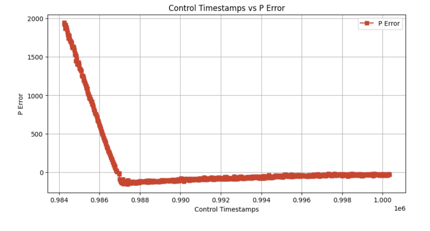
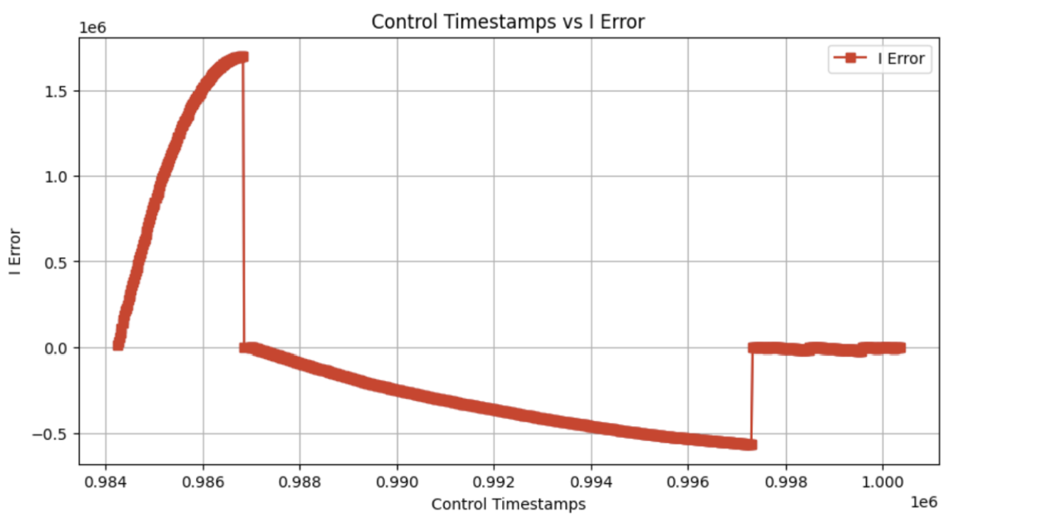
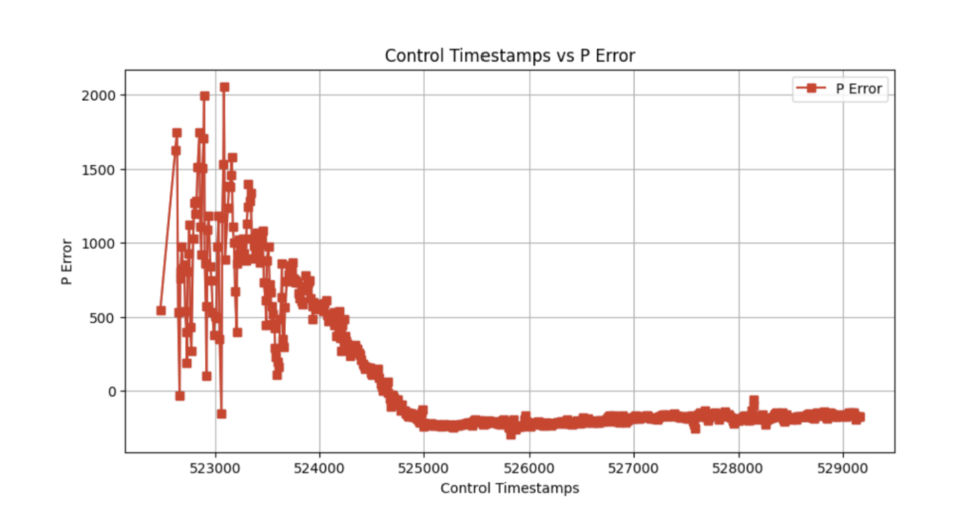
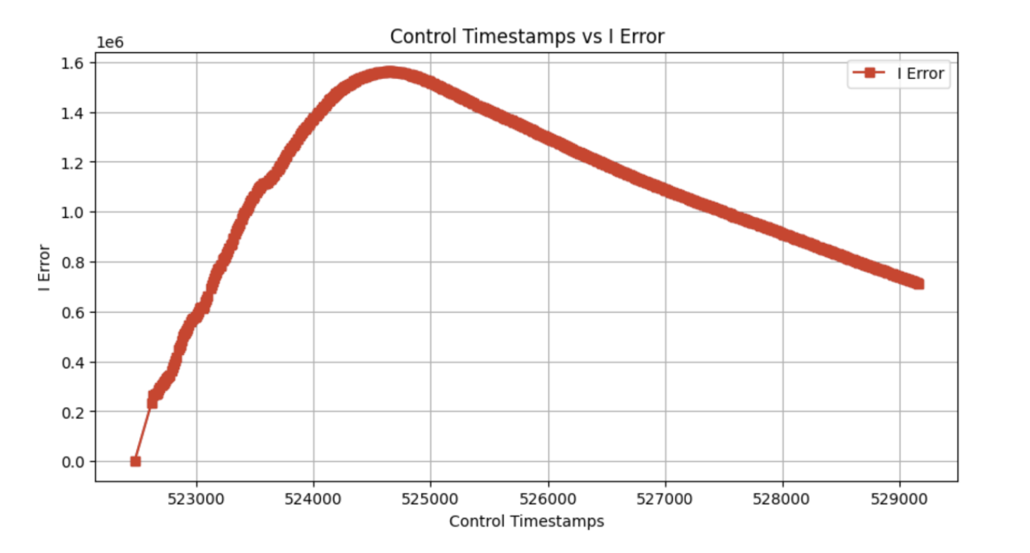
Graphs of the car's distance from the setpoint, integral error, and the car's speed are shown below.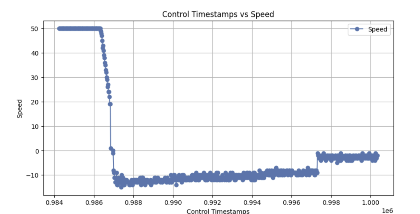
Note: A TOF vs time graph is omitted as it is the same as the PI controller's Proportional Error vs time graph with a translation of 300 mm.
Around 0.997 on the x-axis, the integral error term goes to 0. This is due to the wind-up protection previously mentioned. Since the error has reached a sufficiently small magnitude, the integral term is no longer used.
The videos below demonstrate the car reaching the 1-foot requirement on carpet and a wood floor.
A PID controller would further prevent some of the overshooting present in the PI controller. However, a lack of time meant this controller was not implemented.
Linear Interpolation
Implementation
To further increase the frequency at which the control loop runs, linear interpolation is used to calcualte the car's position even when a TOF reading is not available. Two possible approaches are considered:
- Linearly interpolate between the last two TOF position readings.
- Linearly interpolate between the last two positions (can be calculated or TOF positions).
The function nonBlockReadTOF1(&distance1) returns 0 on a successful read, and 1 otherwise. For an unsuccessful read, the linear interpolation is done by using the last two successful readings. For a succesful read, the reading is stored in the distance1 reference. Furthermore, the reading is stored into last_tof and last_last_tof, time_between_tof, and last_tof_time are adjusted to hold the new TOF reading, the last TOF reading, the time between the current TOF measurement and the last tof measurement, and the current TOF measurement respectively. Notably, a cast to the long data type is needed to prevent integer overflow during the calculation of the distance moved according to the last two tof readings.
Linear Interpolation Speed Discussion & Results
The control loop frequency increased to executing every ~10 ms. This translates to a frequency of ~100 Hz. The TOF sensor, with a timing budget of 20ms, returns data on average every 20 ms. Linear interpolation effectively doubles the frequency of the control loop if the loop is previously limited by the TOF sensor's sampling rate.
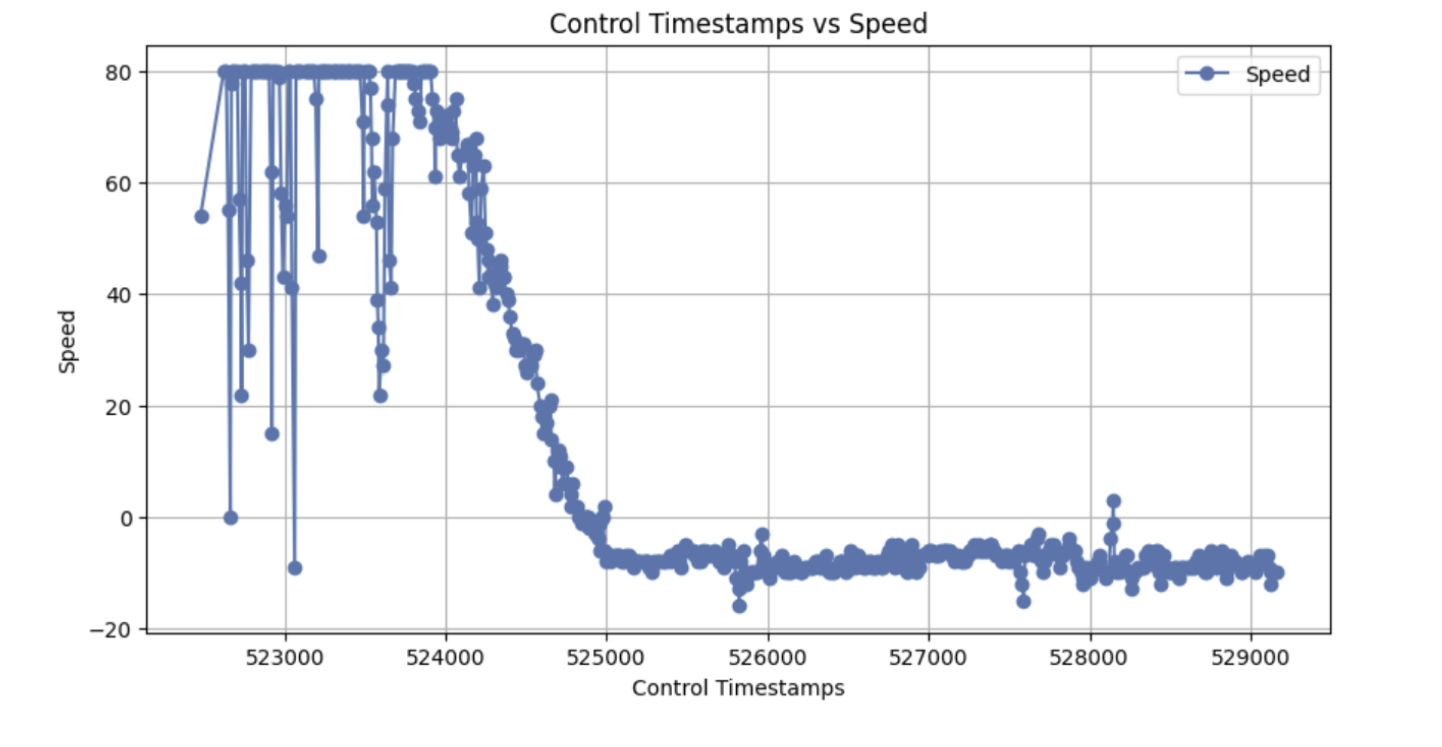
With the same P_GAIN, I_GAIN, and target_tof values, the increased control loop frequency meant the speed of the MAX_SPEED of the car can be increased to 80. This is because the car can make more dynamic adjustments to its speed as it approaches the setpoint.
Graphs of the car's speed, distance from the setpoint, and the integral error are shown below. Notably, the variance in the TOF readings still causes some issues for the linear interpolation calculations. However, the mean values are accurate enough to still be an effective controller.
Note: A TOF vs time graph is omitted as it is the same as the PI controller's Proportional Error vs time graph with a translation of 300 mm.
The videos below demonstrate the car reaching the 1-foot requirement with linear interpolation.