LAB 3: TOF
PRELAB
According to the datasheet, the TOF sensor's I2C address is 0x52.
Since two TOF sensors will be used, the address of one TOF sensor will be changed with software. The TOF's I2C address can be changed with the setI2CAddress function in the SparkFun_VL53L1X library. Another approach to use two TOF sensors is using the XSHUT pins to toggle on/off each of the TOF sensors. However, this approach means additional overhead due to the need to set the GPIO outputs and continuously toggle the sensor.
On the car, the TOF sensors will be placed on the front and right side. In this configuration, obstacles to the left and behind will be missed. If a task involves moving backwards, the right TOF sensor may need to be repositioned to the back.
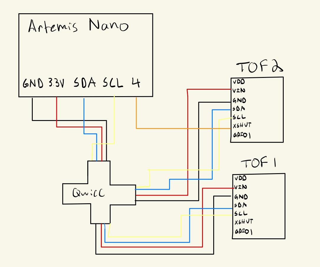
The diagram below shows the wiring diagram of the Artemis board and the 2 TOF sensors.
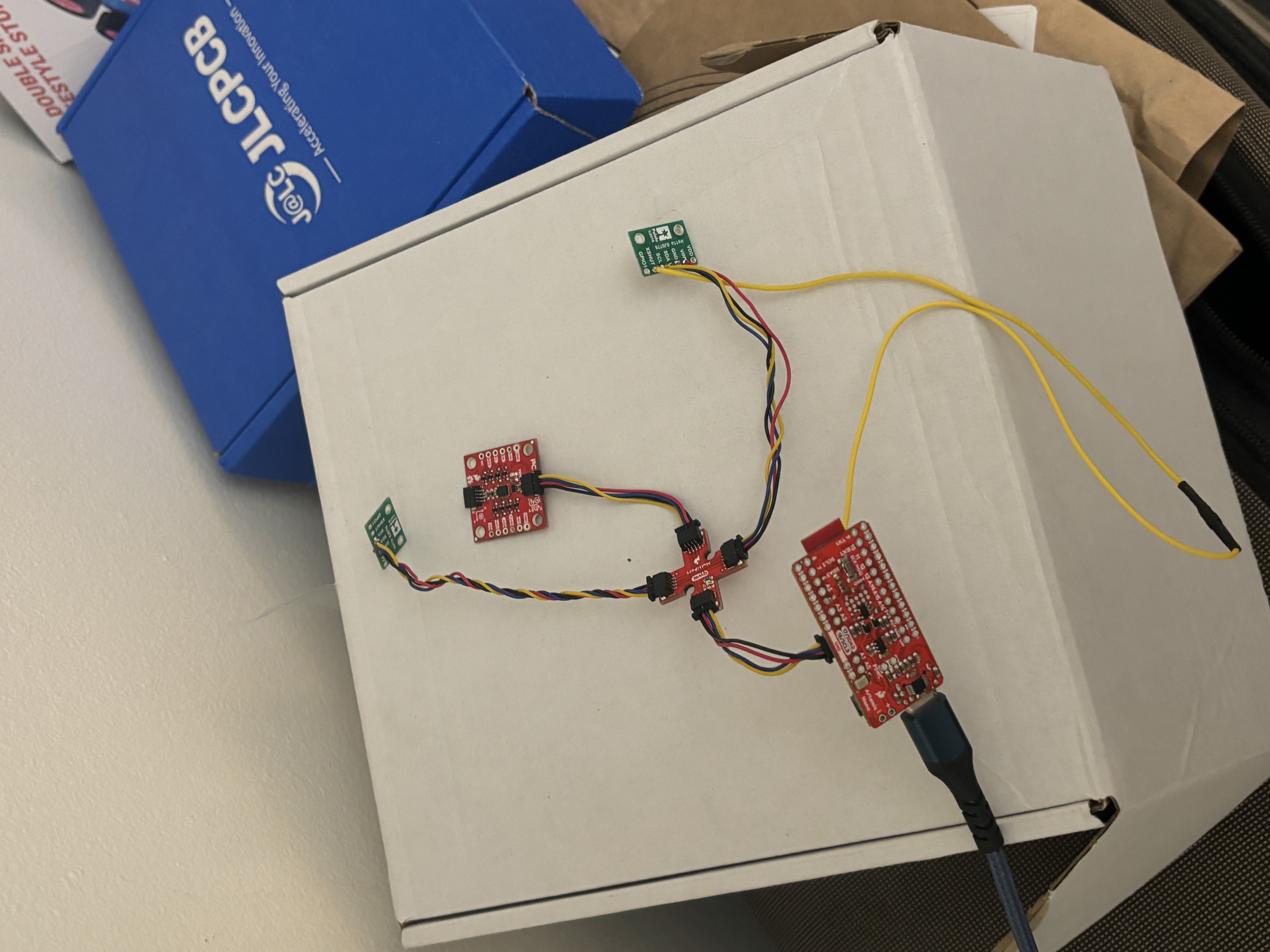
Battery and TOF Connections
The 3.3V and GND wires of the battery were cut and soldered to a JST connector. The Artemis can then run with the battery. The video below demonstrates achieving a bluetooth connection on battery power.
The TOF sensor was connected to the Artemis board using the Qwiic connector and a Qwicc breakout. An additional wire was conected from a GPIO to the XSHUT pin of one of the TOF sensors.
Single TOF
With a single TOF sensor, the I2C channel address can be scanned and printed to the serial monitor. The scanned address is 0x29. The LSB of the 8-bit address is a read/write flag, so 0x52 << 1 yields 0x29
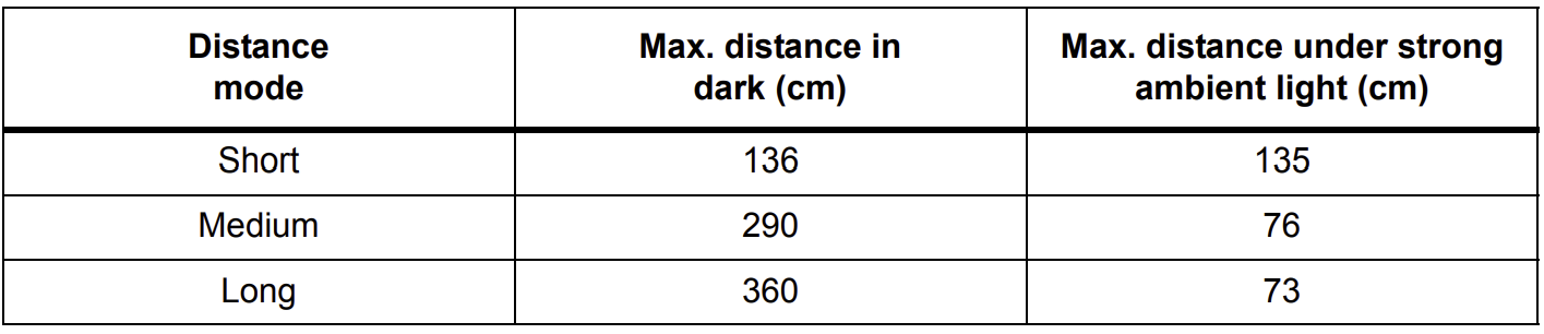
The TOF sensor has two operating modes available through the SparkFun_VL53L1X library: short and long. According to the datasheet, the short distance mode is able to detect the furthest distance under strong ambient light. While the long distance mode has the greatest range in the dark, the operation of the robot is unlikely to take place in dark environments. Thus, the short distance mode was selected for the TOF sensor.
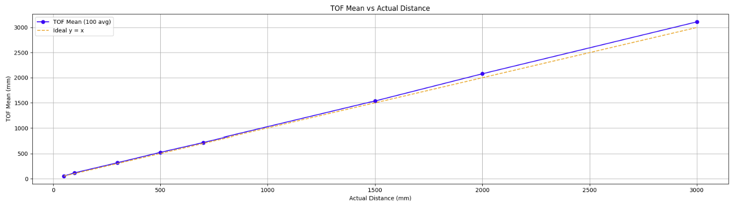
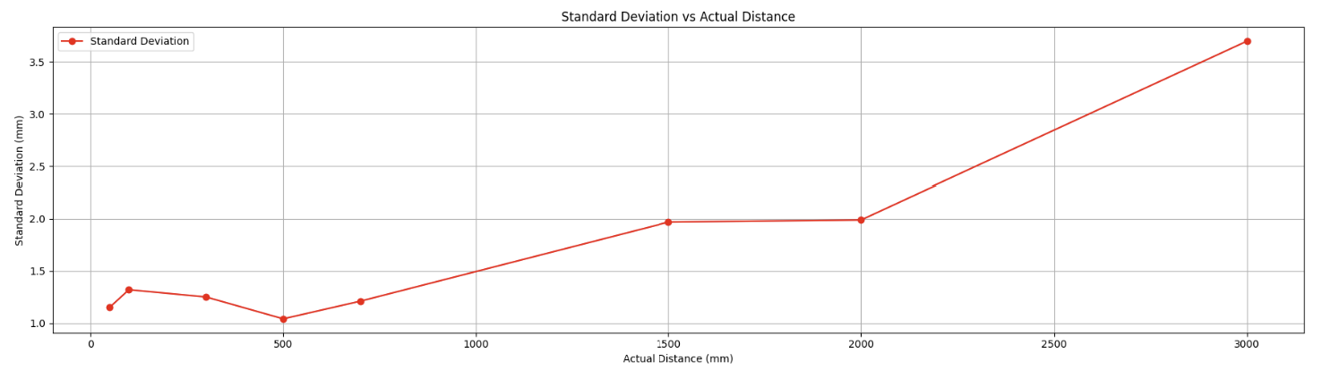
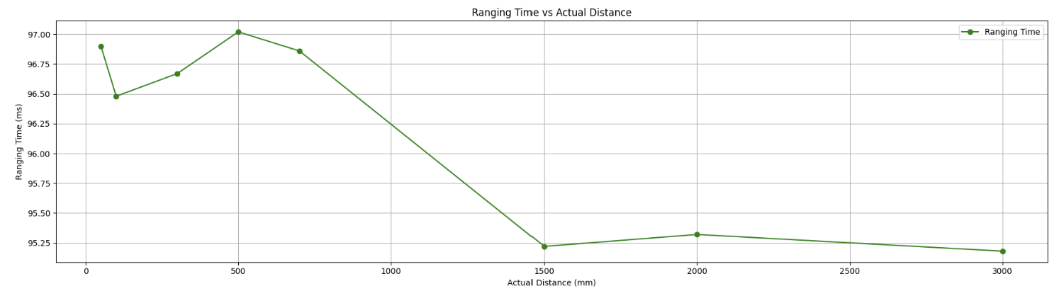
To characterize the accuracy, repeatability, and ranging time, 100 distance measurements are taken and sent over BLE to a laptop. The laptop then calculates the mean, and standard deviation, of the measurements. The data is also labeled with timestamps. By finding the mean difference between timestamps, the ranging time is determined.
The code below shows the implementation of taking distance measurements and sending them over BLE.
The code below shows the implementation of the blockReadTOF1(int * res) function used above.
The python analysis is done by setting up a notification handler, parsing the received string, and populating data arrays. Numpy functions are then used to calculate the mean, standard deviation, and ranging time values.
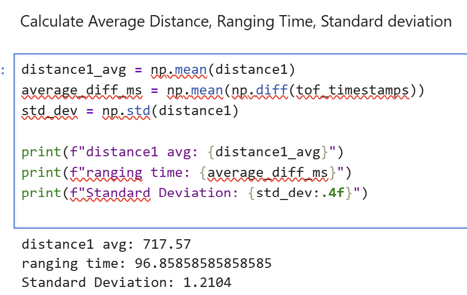
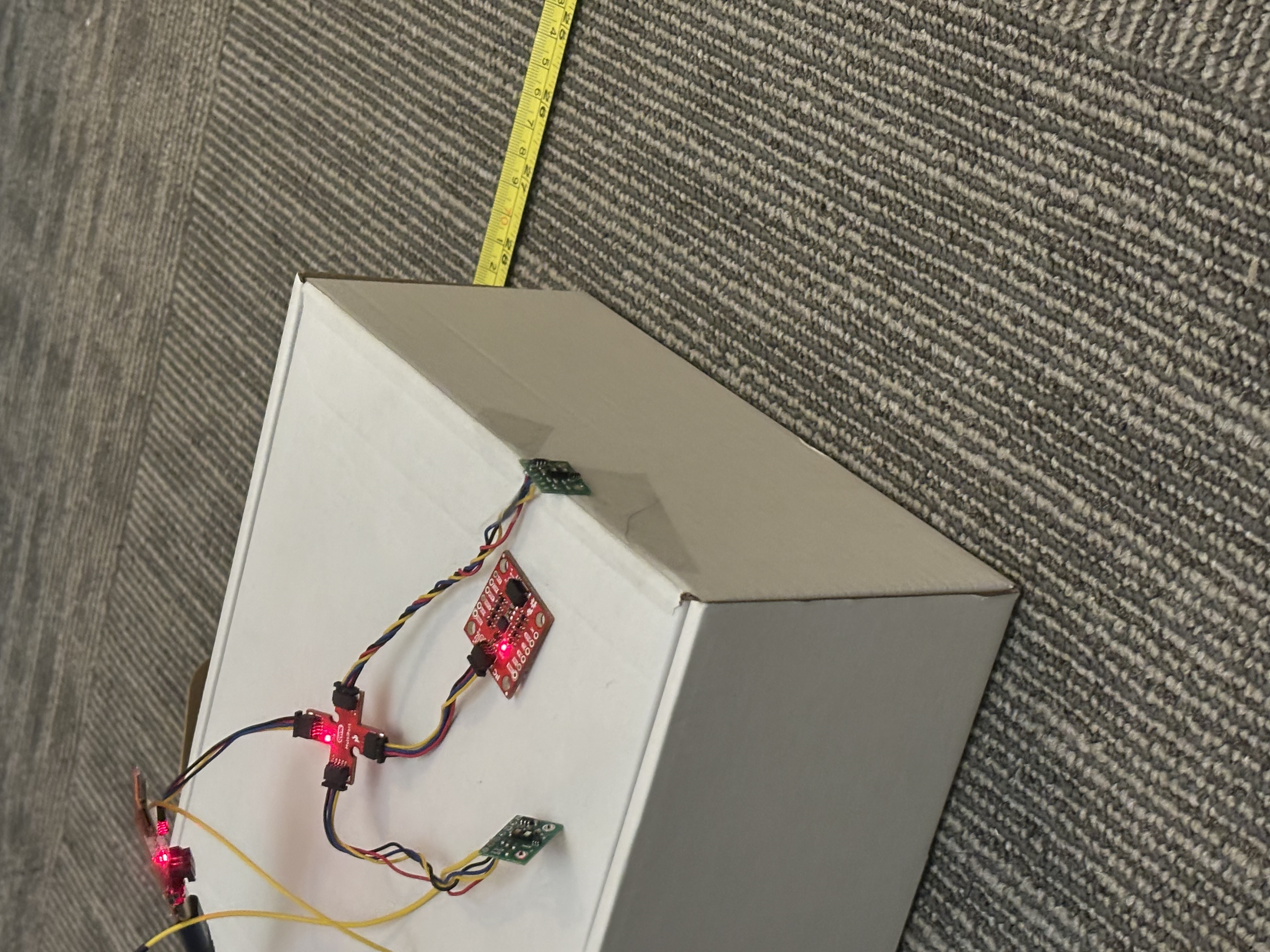
The graphs below illustrate the measured distance, standard deviation, and ranging time on the y-axis and actual distance on the x-axis. The TOF mean measured distance over 100 samples closely resembles the actual distance through 3 meters. Above 1.5 meters, the TOF measured distance is a slight overestimate. The TOF measured distance is reliable within 3 millimeters of standard deivation up to 2.5 meters of actual distance. The ranging time also did not fluctuate greatly with consistent times of ~96 ms. The data was collected with the setup also shown below.
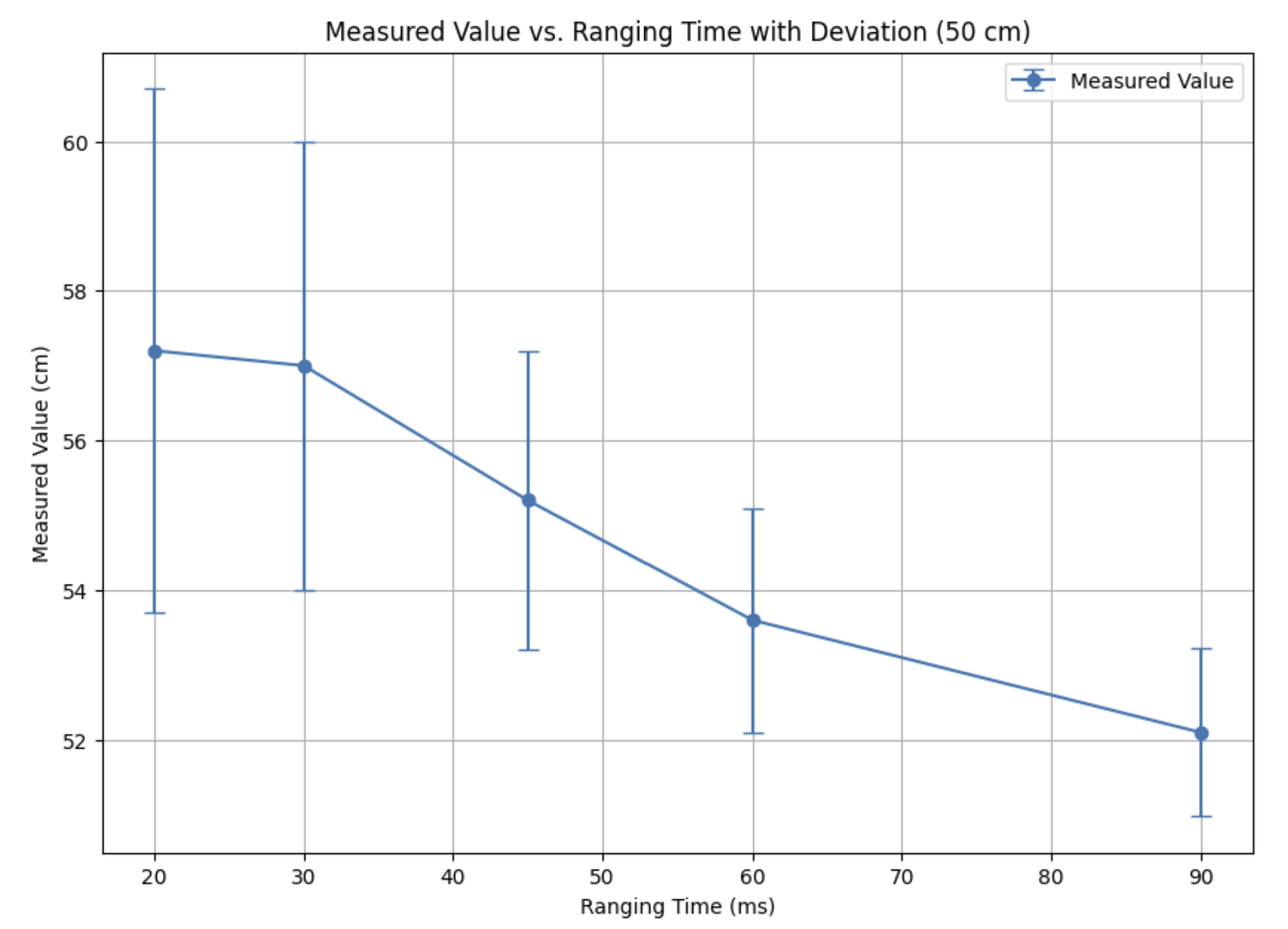
The timing budget can be explicitly set with the function setTimingBudget. To see how different ranging time effects accuracy and repeatbility, 100 samples are taken at an actual distance of 50 cm. Intuitively, a higher ranging time lead to more accurate measurements and smaller standard deviation.
Dual TOF
To use two TOF sensors simultaneously, the active-low XSHUT pin of TOF sensor 2 is tied to GND, the address of the TOF sensor 1 is modified, and the XSHUT pin is set high to restart TOF sensor 2. The code below shows the setup of the two TOF sensors.
The video below demonstrates simultaneously reading from both TOF sensors.
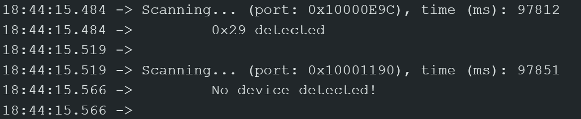
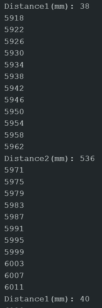
To characterize the speed of the TOF sensors, the Artemis clock is printed. If the distance sensor data is ready, the distance measurement is printed. The code below illustrates this implementation.
A screenshot of the serial monitor is shown below. There is a 93 ms delay between TOF sensor 1 distance measurements. This delay is consistent with TOF sensor 2 and other distance measurements. The loop executes every 4 ms, and a blocking TOF sensor read would be the limiting factor. To mitigate this, the TOF sensor read is done in a non-blocking manner.
Bluetooth and Integration
The START_RECORD command from lab 2 was modified to measure TOF data as well as IMU data. The modified sampling and send loop is shown below.
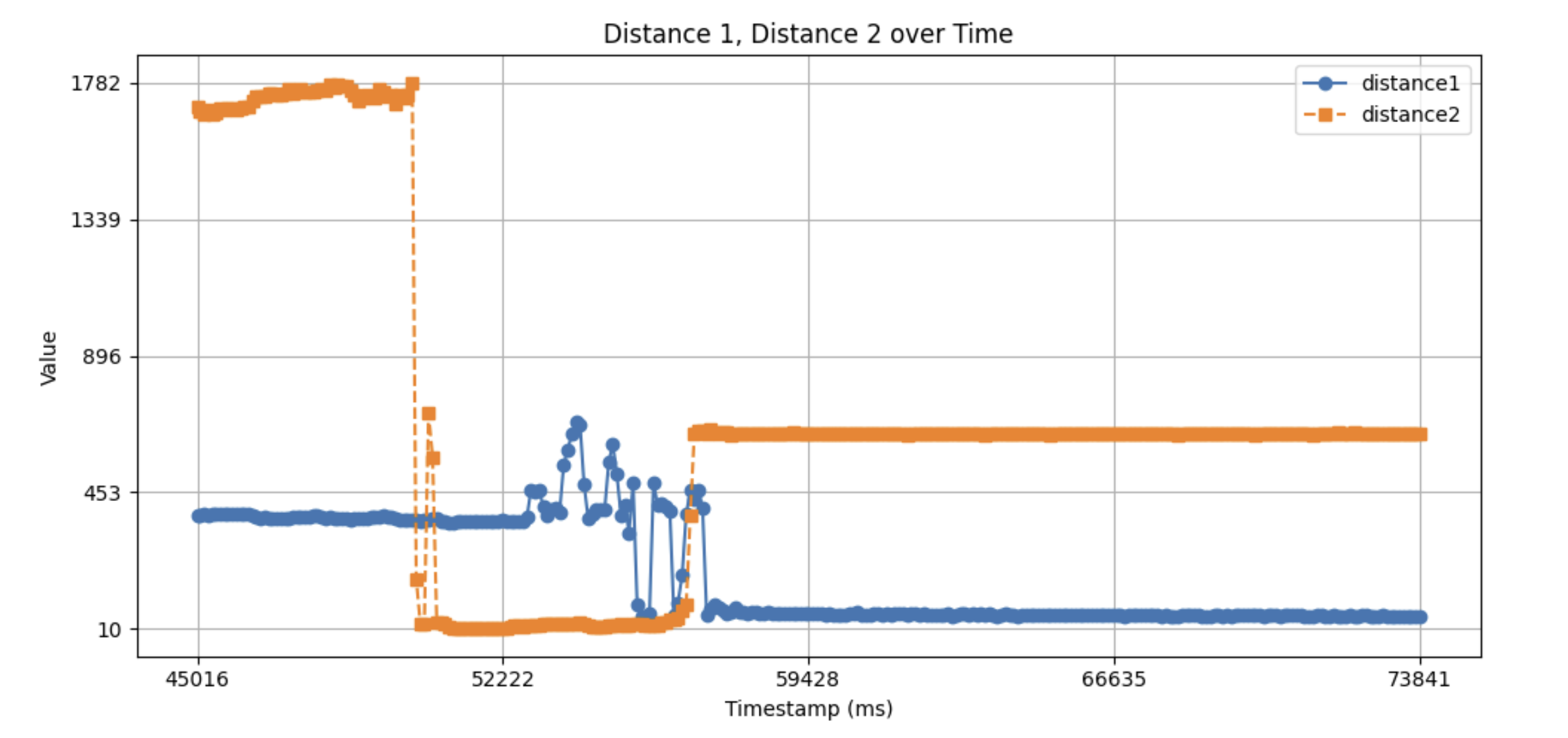
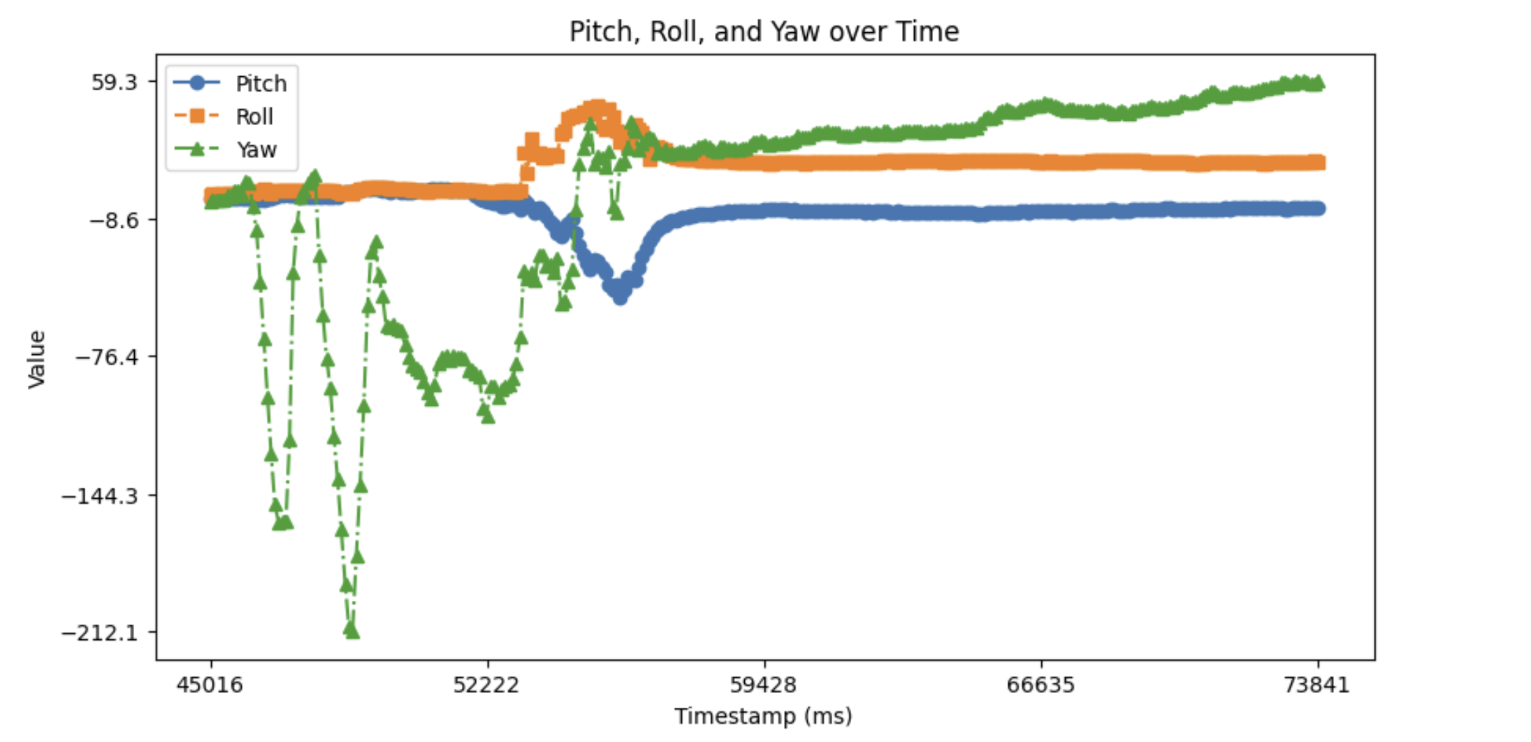
The following graphs plot the TOF and IMU data over the same time period.