LAB 12: Path Planning & Execution
Choosing an Initial Approach
We choose to navigate the robot to the target waypoints using through a pre-determined path and feedback control for driving and orientation. Since localization + runtime path execution depends on the robot's ability to accurately execute a path, this seemed like the logical first step.
Commands are issued from offboard to the robot for each forward drive and turn. The robot then executes PID control to drive forward or turn until the target distance or angle. The distance is found with the TOF sensor and the angle is calculated with the DMP.
Implementation
Artemis Code
Lab 5 code is reused as a starting point to implement the PID controller for driving forward. Initially, the controller's setpoint was set to the target distance to travel. However, inaccurate sensor readings while the robot was in motion caused the robot to overshoot or undershoot the target distance. Thus, the setpoint was changed to the target distance away from the wall in front of the robot's heading. Linear interpolation is also used to speed up the execution of the PID control loop. An excerpt of the command handler is shown below.
The PID(..) function implementation is shown below. A clamping term is also added to the old implementation. This is to prevent the robot from overshooting its setpoint when driving for longer distances.
Lab 6 code is reused as a starting point implement the PID controller for turning. In lab 6, Albert calculated the target setpoint as a relative yaw to the robot's current yaw. While this works for isolated turns, navigating for an extended amount of time meant errors would accumulate. The target setpoint was changed to the absolute yaw of the robot based on the DMP readings. The command handler is shown below.
The PID controller implementation is shown below. The floor_turn variable is made adjustable at run-time to tune the lowest value that is not within deadband and does not cause significant oscillations.
Commands for adjusting the drive and turn PID controller gains are also implemented. These allow us to adjust the gains at runtime to speed up the process of tuning controllers.
Python Code
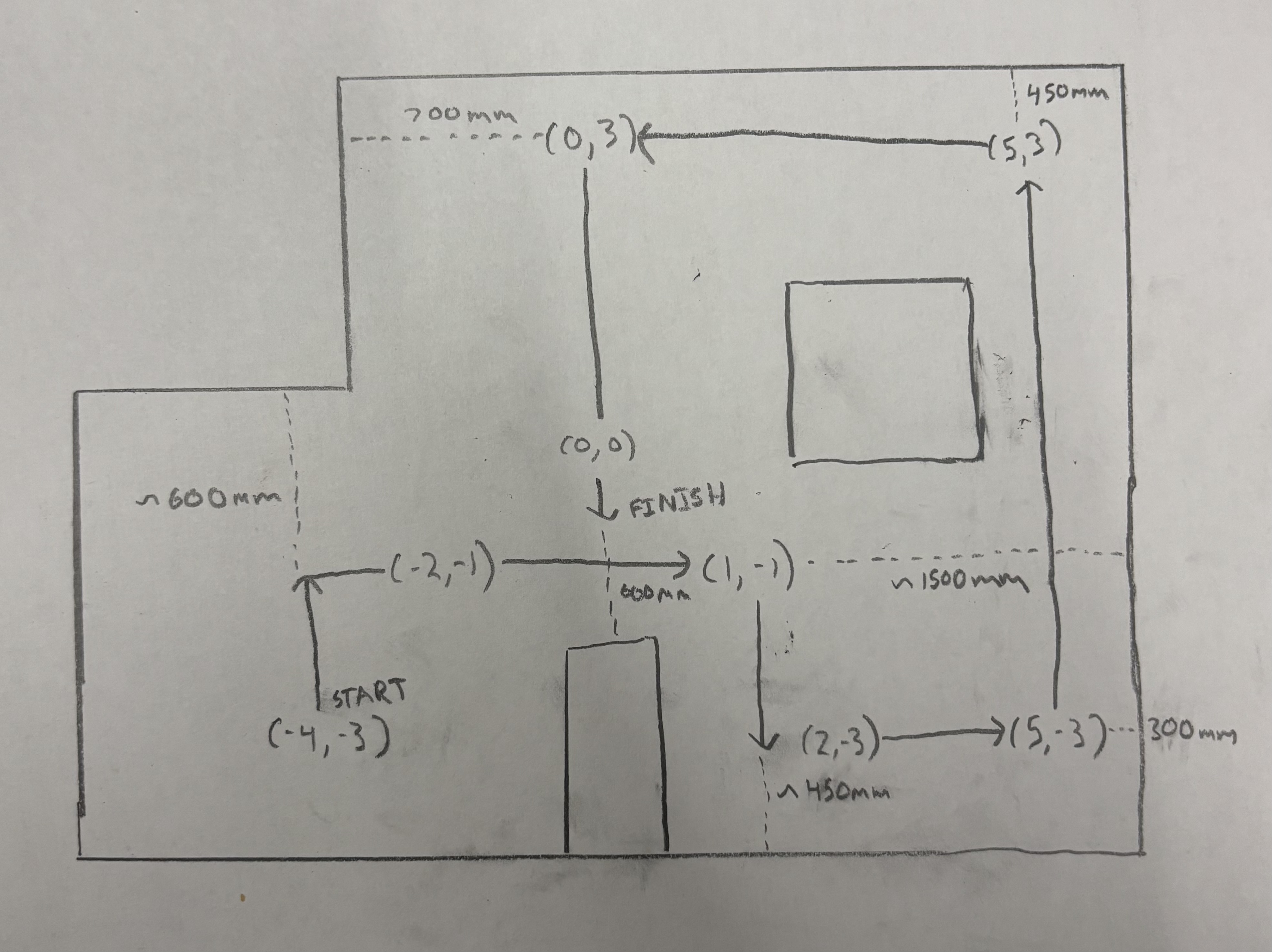
On the Python side, we will send a series of drive and turn commands to the robot to execute the pre-planned path. The diagram below shows the path we will take and the TOF readings we expect during each drive command. The expected TOF readings were based partly on measurements and partly on runtime adjustments from failed runs.
The seris of BLE commands that execute the path are shown below.
Pre-planned Path & Feedback Control Results
The video below shows an unpolished implementation of the pre-planned path and feedback control implementation before extensive tuning and adjustments of PID parameters and the path TOF distances. Notably, without the pauses between drives and turns, it is able to quickly navigate through the environment but does not navigate accurately to all the waypoints.
The video below shows a more polished implementation of the pre-planned path and feedback control implementation after extensive tuning and adjustments of PID parameters and the path TOF distances. The robot is able to navigate through the environment and accurately reach all the waypoints.
Localization
We attempted localization but ultimately ran out of time before a complete implementation. We first implemented a function localize_point(..) that runs the update step to calculate an estimated pose. This function would be called after each drive command. In the implementation, the initial turn orients the robot to face the west wall. PID turn parameters are then set for the small-angle turns of the observation loop. After running the update step, we extract the estimated pose by finding the belief with the highest probability and converting to a grid location with the mapper class. PID turn parameters for large-angle turns are restored and the pose is returned in mm.
Given this pose, we can then calculate the target yaw. The pseuodocode for this function is shown below. The function must map the target bearing to the 0-360 degree range and positive counterclockwise convention we are using.
After calculating the target yaw, we can then call the turn(..) function and pass in the target yaw. Then, we would need to drive forward a distnace to the next waypoint. It is unclear to me how to implement this with our current drive PID controller based on target distance away from forward obstacles. We would need to find the expected TOF reading at the waypoint based on the robot's yaw. For this scenario, a PID drive controller based on distance traveled would be more appropriate. We would not need to calculate the expected TOF reading based on yaw since the distance traveled is relative to the initial TOF reading.
Instead of fully calculating a new path, we can also use the localization results to make small adjustments at problematic waypoints. At the points (2, -3) and (0, 0), we can check if our x-axis belief is equivalent to 2 and 0 respectively. If not, we can drive forward a small distance to correct our x-position. The same goes for the y-axis. The Python code for these small local adjustments is shown below.
The run below shows the robot executing the pre-planned path with localization and small local adjustments. The robot is able to navigate through the environment and accurately reach all the waypoints.
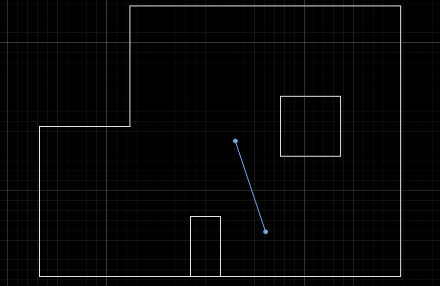
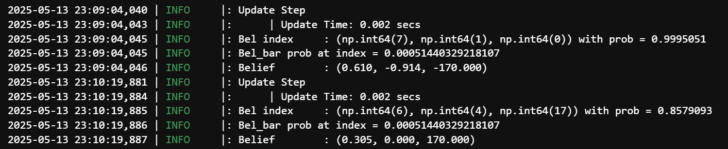
The plot and the update step data outputs are shown below.
Challenges
Several challenges were encountered during the implementation of the pre-planned path and feedback control.
Inconsistent TOF readings
As mentioned earlier, the PID controller for driving forward's setpoint was initially base don distance traveled. This is implemented by taking an initial TOF reading then comparing subsequent TOF readings to the initial reading. However, this meant the first reading was extremely important, and a grossly inaccurate reading would ruin the run. PID control based on target distance is more robust to these one-off errors since the robot continuously takes TOF readings and calculates a new control signal.
DMP Drift
In cases where we have the robot on for an extended period of time, the DMP readings would drift to inaccurate values. This is likely due to the IMU's placement near the motor drivers. A quick and dirty solution would be to restart the Artemis before a run. This would be a bigger problem if we relied on localization.
Finding Suitable PID parameters
It is important for the first 90-degree turn to be accurate. Overshooting or undershooting would lead to the TOF sensor measuring an obstacle instead of the eastern wall. A high proportional gain would lead to oscillations. Too low of a gain would lead to undershooting the setpoint. A combination of raising the floor PWM and decreasing the proportional gain allowed us to reach the setpoint with minimal oscillations.